
I use cardboard stereo mounts routinely. I prefer them mainly for reason of cost. The large variety of openings available with the Spicer mounts is also an advantage. I have built a mounting jig that allows me to mount in cardboard with great precision. I shoot mostly 7 perf now, but sometimes still shoot 5 perf.
For 5 perf slides, I use the heat seal mounts. I prefer the convenience of heat sealing as opposed to taping or gluing. The alignment tabs can be convenient, but they get in the way when adjustment is necessary. I often end up pushing the tabs down so that I can adjust the film chips further than they go otherwise. They would be better if there were multiple tabs in the horizontal direction rather than vertical. I find the edges are tolerable, but the Spicers look better, though still not as good as Albion or RBT.
For 7 perf slides I use the Spicer mounts. They are accurate and have clean edges. I like the variety of openings. I used to glue them shut because it looks neater and makes them stiffer. I decided it was too much mess. I now tape them shut with silver Mylar tape. I am generally happy with the results.
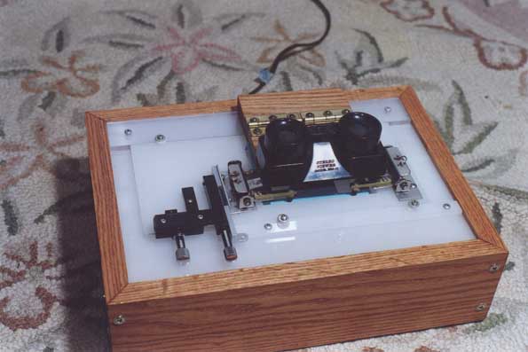
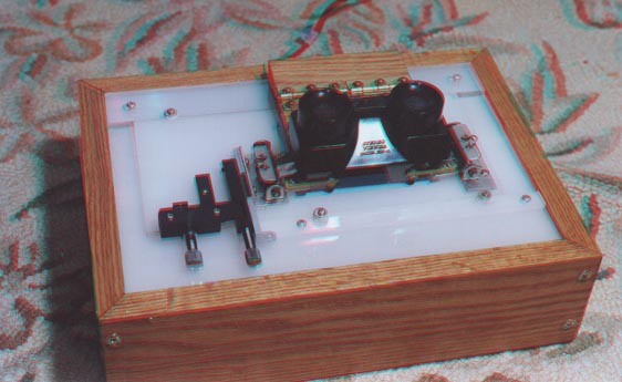
My Stereo Slide Mounting Jig
Larger 2-D Photo: mounter.jpg
Stereo Pair for Parallel Viewing: mnt_par.htm
Stereo Pair for Cross-Eyed Viewing: mnt_cros.htm
Anaglyph: mount_an.jpg
Description of my Mounting Jig, and my Mounting Technique.
I have been using cardboard heat seal mounts for most of my stereo slides for several years, and have had no problems in projection in either the Nord or the TDC 716 projectors. The key is that whatever type of mount you use, the mounting must be accurate. I use a fixture that I built which holds the film chips in position on the mount, which is above the Reel 3D mounting gauge. The fixture allows moving the slide from side to side over the mounting gauge in order to line up the near and far points. Magnifier lenses above the slide allow viewing the slide in stereo while adjusting the window. I then tack the film chips in place and then heat seal the mount. It takes me the better part of an evening to mount a roll, but the results have been quite satisfactory, and my mounting costs are low. I now use Spicer cardboard mounts for most of my 7 perf slides. Before the Spicer mounts became available, I used the aluminum masks (EMDE and Albion) for 7 perf, and would probably use heat seal for 7 perf if the mounts were available. I will admit that the sharp edges of the aluminum masks do look nicer, but my audiences are used to heat seal mounts on 2-D slides, and don't notice a bit. If I were mounting for stereo competitions I would probably use RBT mounts.
More details about my stereo slide mounting jig:
The base of the unit is a box with 4 short sides made of oak. The top of the box is .25 in. thick white acrylic. The bottom is .25 in. plywood. Inside the box, centered below the mounting area is an 8 watt fluorescent fixture. The slide mount is placed inside of a square clear acrylic frame, the inside dimensions are that of a heat seal mount opened flat, the outside dimensions are slightly (about .5 in.) larger on the top and bottom and about 2 in. wider on each of the left and right ends. The bottom of this slide carriage is a thin (.062 in.) sheet of acrylic. On each of the ends of the carriage is mounted a toggle clamp that was salvaged from an old film splicer. This toggle clamp has been modified so that two arms come out from each with vinyl tips on the end that hold the film chips against the mount in the vicinity of the perforations. One of these is mounted directly to the carriage, but the other is attached to an x-y microscope stage to allow for easy adjustment of that film chip. An improvement would be to have an z-y stage on both sides.
A mounting gauge from Reel 3-D is sandwiched between the white acrylic top of the box and a thin (.062 in) sheet of acrylic. On top of this are two long strips of acrylic that are spaced apart the width of the slide carriage described above. Two thin strips of Teflon tape are applied to the bottom of the carriage at the edges, so that when the carriage slides between the guides, the bottom of the carriage will not rub on the top of the alignment gauge (which is protected by a thin sheet of acrylic). The carriage is retained in this slot by screws with plastic washers.
On a hinged board is mounted a pair of lenses in a focusing mount which was made by modifying the Franka full frame viewer sold by Reel 3-D. My prototype used lenses from a View-Master model B, and the Revere/Wollensak lenses from Dr. T. might be better, but you would have to come up with a focusing mount. This lens assembly swings up out of the way when inserting and removing the film chips and mounts.
In use, the mount is placed in the carriage. Next, the film chips are cut (with a Hama illuminated cutter) and placed on the mount, against the embossed tabs. The toggle clamps are lowered to hold the chips in place. The viewer is lowered into position, and the slide is inspected for alignment, first for vertical, and adjustments are made with the y adjust knob. The carriage is slid from side to side to align the gauge with the infinity points. The x is then adjusted. Next, I check for the near point to make sure that through- the-window protrusion is OK. Further window adjustment may be made for aesthetic reasons. Sometimes the play between the embossed tabs on the heat seal mount is not sufficient, and I will need to flatten them to go beyond their range.
Next, if I am using heat seal mounts, I will tack the chips into place with my tacking iron. This was made from the ferrite core of a variable inductor, into whose spiral groove was wound a thin nichrome wire. This is mounted on a handle, and is powered by a 6V transformer, with a resistance in series to limit the current. This attaches the film lightly to the mount in about 1 sec. If necessary, I can crop the slide with aluminized Mylar tape at this time.
I then remove the mount, fold it over and seal it shut with an old iron that has been modified with an aluminum plate on the bottom that has been cut to the shape of the mount, with cutouts where the film chips are, to reduce the amount of heat transferred to the film. With the heat seal mounts, the opening on the side with the alignment tabs is smaller than those on the other side. This is the side that should be toward the viewer. When using the heat seal mounts, you need to mount upside down, that is with the left chip on the right and the right chip on the left, and writing backwards. After the mount is closed, it will look fine from the other side.
I use this same jig for mounting in Spicer mounts using a variation on the RBT transfer technique. This is how I mount most of my slides today.
+++++++++++++++++++++++++++++++++++++++++++++++++++++++++++++++++++++++++
Using my mounting jig with a variation on the RBT transfer technique.
What I have done with an RBT mount is to remove most of the mount except for the bottom portion, leaving just a small part of the vertical portions. I have 2 of these, one with the pinbars taped down for constant infinity mounting of average shots, and the other with the pinbars loose so that the window placement can be adjusted (use mostly for close-ups).
In use, I place a Spicer mount in my mounting jig. I then
place
the modified RBT on top of it, pins up, pressed against the bottom edge
of the mount recess in the fixture. Now I cut my film chips and
place
them on the pins. The clamps on the fixture hold the chips onto
the
pins, so slight curl is not a problem. I then flop down the
viewer
lenses, and preview the slide. I double check for infinity
separation,
window violation, and if any cropping would improve the
composition.
I then tape down the chips as they sit in the fixture, using 1/4 inch
silver
Mylar tape. This avoids flipping the sandwich over. The
problem
I have in
taping down the chips is that because the RBT keeps one end of the
chips raised off the surface of the Spicer mount, a vertical error is
sometimes
introduced. I then have to untape the chips and try again.
With the second modified RBT that has loose pinbars, the left pinbar can be moved back and forth with the modified microscope stage while viewing the slide, providing real-time adjustment of window placement. If i need to do much of this adjustment, it is often necessary to use reduced width mounts.
Since the chips are positioned above the wider openings in the Spicer mount (prior to the front being folded over), there is a bit more of the image shown that will actually be visible, so some estimation of the actual image edges is necessary.
+++++++++++++++++++++++++++++++++++++++++++++++
This jig can also be used with aluminum masks such as the EMDE and
Albion.
Another page with more photos and
details about the mounting jig.
Modification of film cutter:
When using heat seal mounts, it is important that the film chips be cut accurately. A trick that I have used with the Hama film cutter is to tape a pin bar from an RBT mount to the cutter so that it registers exactly 5 perforations apart for each cut.
Copyright 2000-2005, Paul Ivester. All rights reserved.